Confirm these three details before release.
- Specify maximum case length, rod attachment and moving mass.
- Keep the core clear of the bore over the full working travel.
- Agree excitation voltage/frequency, sensitivity and cable capacitance.
LVP-MIN / Passive AC
Small-diameter inductive displacement sensor configurations for constrained test fixtures, triaxial cells and compact actuator development. Begin with the available envelope and permissible moving-core mass.
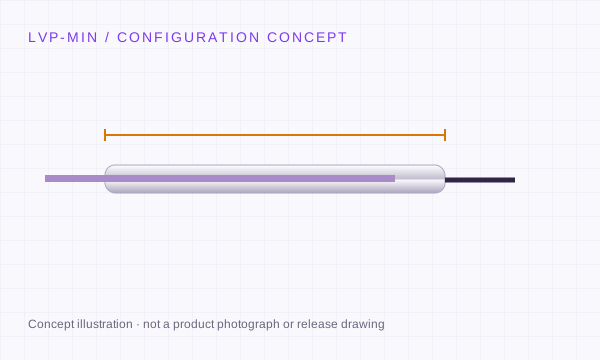
Nominal 3/16 inch is 4.7625 mm and 3/8 inch is 9.525 mm. Confirm actual fit tolerances from drawings.
Rock and soil triaxial tests, materials extensometry, miniature actuators and research instruments.
Original model review: Macro Sensors CD 375 / MD 375; Schaevitz MHR / XS-B; G.L. Collins miniature configurations. References identify review candidates; compatibility is not pre-approved.
Check the replacement process ↗SIGNAL INTEGRATION
Wire count and cable colour do not identify a universal pinout. Use the released sensor and conditioner drawings.
+V → sensor
Common ↔ PLC reference
Signal → voltage / current input
Separate supply and output; check output load. Colours such as red, black and green are examples only.
Supply + / supply return
Signal + / signal return
Confirm isolation and reference
A fourth wire may have another purpose. A two-wire 4–20 mA loop needs its own wiring diagram.
2 primary excitation leads
4-wire: opposed secondaries internally joined
5-wire: centre tap; 6-wire: separate coils
Match phase, amplitude, frequency and topology to the conditioner. Pair with LVP-AMP after review.
3-wire may be an inductive half-bridge
RS485: power, A/B and reference per model
Orbit requires its network interface
Half-bridge, analogue AC and digital networks are distinct interfaces.
MECHANICAL SELECTION
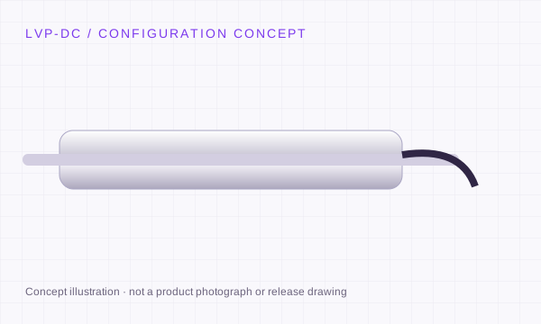
Separate the moving core from the coil body. External guidance must maintain clearance; the electromagnetic sensing element has no sliding electrical contact.
A guided assembly simplifies linkage. Review side load, rod alignment, bearings and usable travel before integrating.
A contact tip follows the measured surface. Review tip force, pre-travel, overtravel and contact wear.
Concept schematics. Non-contact induction does not make bearings, springs or contact tips wear-free.
CONFIGURATION RELEASE
Agree bipolar range, null, sensitivity and residual error against a reference displacement stage. State whether error is % of full range or reading.
Define approach direction, probe force, electronics, filtering, temperature and sample method. Resolution alone does not describe repeatability.
Check temperature drift, warm-up and mounting stress. Confirm pressure, medium, cable and sealing conditions for the complete assembly.
A proposed review plan, not a claim that a specific LVP model has completed qualification.
REQUEST A CONFIGURATION REVIEW
LVP-MIN · Miniature & Micro LVDT Sensors
Send the working range, mechanical arrangement and electrical interface. Add the original model when reviewing a replacement.
[email protected] ↗No. The listed values define the selection request envelope. The quote and released drawing identify the exact range, body size, electrical interface and acceptance conditions.
Yes. Include your installation envelope and required file format in the RFQ. Configuration-specific documentation follows engineering review; an illustration on this page is not a release drawing.
Review the sensor manufacturer’s mounting recommendations. Magnetic materials and excessive clamping force can affect some designs. Specify the clamp material, bore tolerance and torque rather than assuming every metal clamp is unsuitable.
Provide the configuration, quantity and delivery destination. Engineering will confirm the quotation, available documentation and schedule for that request.
LVP-DC
±2.5 to ±500 mm
4–20 mA · 0–10 V · ±10 V · RS485
Explore configuration ↗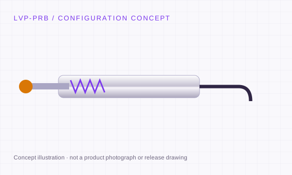
LVP-PRB
±0.5 to ±25 mm
AC · half-bridge · DC · digital variants
Explore configuration ↗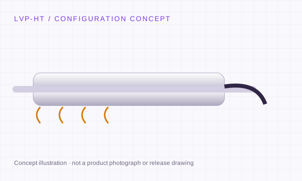
LVP-HT
±2.5 to ±300 mm
Passive AC · remote LVP-AMP
Explore configuration ↗
LVP-AMP
1 / 2.5 / 5 / 10 kHz excitation requests
0–10 V · ±10 V · 4–20 mA · RS485
Explore configuration ↗