INDUCTIVE DISPLACEMENT / OEM CONFIGURATION[email protected]
LVDTPRECISION METROLOGY

LVP-PRB / AC / conditioned variants

Spring-Loaded LVDT Gauging Probes

Spring-return and pneumatic gauging probe configurations for multi-point fixtures, thickness stations and dimensional inspection. Match tip force and guidance to the measured surface.

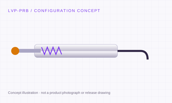
Spring-Loaded LVDT Gauging Probes concept showing the mechanical form
Engineering concept · final geometry requires a released drawing.

LVP-PRB: stroke, body and signal review.

Requested measuring range
±0.5 to ±25 mm
Body / installation
Ø8 h6 / Ø9.525 mm
Signal variants
AC · half-bridge · DC · digital variants
Mechanical configuration
Spring return or pneumatic actuation

Resolution depends on electronics; repeatability depends on the complete probe, contact mechanics and test method.

Confirm these three details before release.

  1. Request repeatability at a defined contact force, approach direction and test method.
  2. Choose M2.5 or #4-48 tip threads from the exact probe drawing.
  3. Orbit and half-bridge interfaces require separate controller compatibility review.

Where the configuration fits.

Automotive components, bearing inspection, glass thickness and precision gauging fixtures.

Original model review: Solartron AX / DP; Macro Sensors GHSA / GHSDR; Mahr, Marposs and Tesa probe configurations. References identify review candidates; compatibility is not pre-approved.

Check the replacement process ↗

SIGNAL INTEGRATION

3, 4, 5 or 6 wires: identify the circuit first.

Wire count and cable colour do not identify a universal pinout. Use the released sensor and conditioner drawings.

Conditioned DC · 3-wire

+V → sensor

Common ↔ PLC reference

Signal → voltage / current input

Separate supply and output; check output load. Colours such as red, black and green are examples only.

Conditioned DC · 4-wire

Supply + / supply return

Signal + / signal return

Confirm isolation and reference

A fourth wire may have another purpose. A two-wire 4–20 mA loop needs its own wiring diagram.

AC-LVDT · 4 / 5 / 6-wire

2 primary excitation leads

4-wire: opposed secondaries internally joined

5-wire: centre tap; 6-wire: separate coils

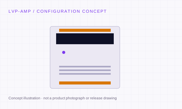
Match phase, amplitude, frequency and topology to the conditioner. Pair with LVP-AMP after review.

Half-bridge / digital

3-wire may be an inductive half-bridge

RS485: power, A/B and reference per model

Orbit requires its network interface

Half-bridge, analogue AC and digital networks are distinct interfaces.

Read the LVDT excitation & connection guide ↗

MECHANICAL SELECTION

Free core, guided rod or spring contact?

Free unguided core

Separate the moving core from the coil body. External guidance must maintain clearance; the electromagnetic sensing element has no sliding electrical contact.

Captive guided rod

A guided assembly simplifies linkage. Review side load, rod alignment, bearings and usable travel before integrating.

Spring-return probe

A contact tip follows the measured surface. Review tip force, pre-travel, overtravel and contact wear.

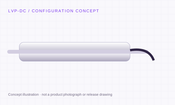
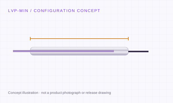
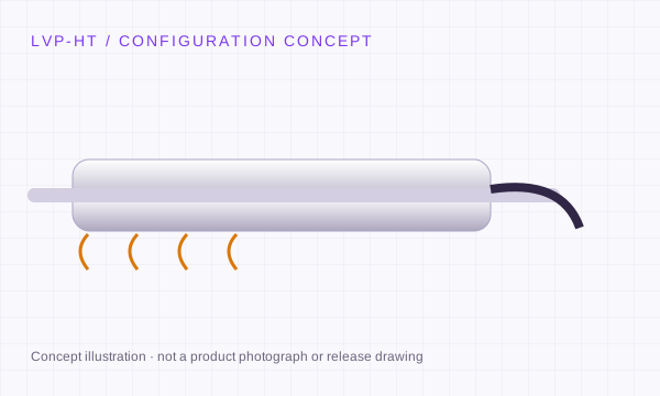
Concept schematics. Non-contact induction does not make bearings, springs or contact tips wear-free.

CONFIGURATION RELEASE

Define the acceptance test before the sensor.

Stroke & linearity

Agree bipolar range, null, sensitivity and residual error against a reference displacement stage. State whether error is % of full range or reading.

Repeatability & noise

Define approach direction, probe force, electronics, filtering, temperature and sample method. Resolution alone does not describe repeatability.

Thermal & installation

Check temperature drift, warm-up and mounting stress. Confirm pressure, medium, cable and sealing conditions for the complete assembly.

A proposed review plan, not a claim that a specific LVP model has completed qualification.

REQUEST A CONFIGURATION REVIEW

Tell us what
moves. And how
you need to read it.

LVP-PRB · Spring-Loaded LVDT Gauging Probes

Send the working range, mechanical arrangement and electrical interface. Add the original model when reviewing a replacement.

[email protected] ↗
Drawings, CAD and calibration documentation are configuration-specific. Engineering will confirm the proposed scope, price and schedule.
LVDT engineering RFQ

Complete the installation.

Optional accessories · reference budgets in USD · final price by quotation.

Selected accessory budget: $283Sensor, tax and freight excluded. No payment at this stage.

Before ordering LVP-PRB.

Are the listed ranges guaranteed for every configuration?

No. The listed values define the selection request envelope. The quote and released drawing identify the exact range, body size, electrical interface and acceptance conditions.

Can I request a CAD drawing and calibration information?

Yes. Include your installation envelope and required file format in the RFQ. Configuration-specific documentation follows engineering review; an illustration on this page is not a release drawing.

Do I need a non-magnetic clamp?

Review the sensor manufacturer’s mounting recommendations. Magnetic materials and excessive clamping force can affect some designs. Specify the clamp material, bore tolerance and torque rather than assuming every metal clamp is unsuitable.

What are the price, minimum quantity and lead time?

Provide the configuration, quantity and delivery destination. Engineering will confirm the quotation, available documentation and schedule for that request.
Complete the LVDT measurement chain.