Confirm these three details before release.
- Specify maximum case length, rod attachment and moving mass.
- Keep the core clear of the bore over the full working travel.
- Agree excitation voltage/frequency, sensitivity and cable capacitance.
LVP-MIN / Passive AC
Small-diameter inductive displacement sensor configurations for constrained test fixtures, triaxial cells and compact actuator development. Begin with the available envelope and permissible moving-core mass.
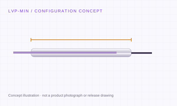
Nominal 3/16 inch is 4.7625 mm and 3/8 inch is 9.525 mm. Confirm actual fit tolerances from drawings.
Rock and soil triaxial tests, materials extensometry, miniature actuators and research instruments.
Original model review: Macro Sensors CD 375 / MD 375; Schaevitz MHR / XS-B; G.L. Collins miniature configurations. References identify review candidates; compatibility is not pre-approved.
Check the replacement process ↗LVP-MIN / DEFINE THE INTEGRATION
A miniature LVDT must fit as a coil, moving core, attachment and cable assembly. Start with the available space and permissible influence on the specimen or mechanism; nominal diameter alone is insufficient.
Provide maximum body length, diameter tolerance, core length, datum-to-null distance and connector or cable exit clearance. Attach the existing drawing rather than relying on dimension letters alone.
Ø4.7625 mm and Ø9.525 mm are separate request envelopes; their maximum travels and core masses are not automatically combinable.
Define radial clearance, alignment over travel, attachment thread, extension rod and permissible moving mass. Include the motion trajectory and any lateral deflection.
A free core needs external guidance; non-contact induction does not prevent contact caused by a misaligned fixture.
Provide the controller carrier voltage/frequency, sensitivity, topology and cable length. If conditioned output is required, include the remote or in-line module envelope.
A small coil-body diameter does not establish the size of a complete DC-output measurement chain.
Technical background for these interface distinctions. Manufacturer references do not establish LVP ratings.
REQUEST A DEFINED CONFIGURATION
These request references prefill your RFQ. They describe the configuration you want quoted; final model number, A/B dimensions, thread, performance and availability are confirmed on the quotation drawing.
| Request reference | Requested travel | Body / mechanics | Requested interface | Drawing & review |
|---|---|---|---|---|
| LVP-MIN-REQ-0P5 ↗ | ±0.5 mm (1 mm total / 0.039 in) | 4.7625 mm (3/16 in) Free unguided core | Passive AC-LVDT + matched conditioner | Final body/core dimensions, thread and performance on the configuration drawing |
| LVP-MIN-REQ-1 ↗ | ±1 mm (2 mm total / 0.079 in) | 4.7625 mm (3/16 in) Free unguided core | Passive AC-LVDT + matched conditioner | Final body/core dimensions, thread and performance on the configuration drawing |
| LVP-MIN-REQ-2P5 ↗ | ±2.5 mm (5 mm total / 0.197 in) | 4.7625 mm (3/16 in) Free unguided core | Passive AC-LVDT + matched conditioner | Final body/core dimensions, thread and performance on the configuration drawing |
| LVP-MIN-REQ-5 ↗ | ±5 mm (10 mm total / 0.394 in) | 9.525 mm (3/8 in) Free unguided core | Passive AC-LVDT + matched conditioner | Final body/core dimensions, thread and performance on the configuration drawing |
| LVP-MIN-REQ-10 ↗ | ±10 mm (20 mm total / 0.787 in) | 9.525 mm (3/8 in) Free unguided core | Passive AC-LVDT + matched conditioner | Final body/core dimensions, thread and performance on the configuration drawing |
| LVP-MIN-REQ-25 ↗ | ±25 mm (50 mm total / 1.969 in) | 9.525 mm (3/8 in) Free unguided core | Passive AC-LVDT + matched conditioner | Final body/core dimensions, thread and performance on the configuration drawing |
| LVP-MIN-REQ-50 ↗ | ±50 mm (100 mm total / 3.937 in) | 9.525 mm (3/8 in) Free unguided core | Passive AC-LVDT + matched conditioner | Final body/core dimensions, thread and performance on the configuration drawing |
Provide maximum body length, core or rod length, datum-to-null distance, thread, connector clearance and permitted overtravel. Dimension letters differ between original manufacturers. Use the exact released drawing for an installation comparison.
Compare a source-linked original model ↗TAKE THE CONFIGURATION TO YOUR ENGINEERING TEAM
Download the family guide, requested configurations and editable RFQ fields. Fill in the PDF, save it in your reader and email the saved file to inquiry@lvdtsensor.com.
Preliminary selection worksheet. Configuration-specific dimensions, ratings, released CAD and measured reports follow review.
EXCITATION & CONNECTION TOPOLOGY
Use these circuit principles to identify the required sensor and conditioner. Cable colour, shield count and connector shell do not establish a pinout.
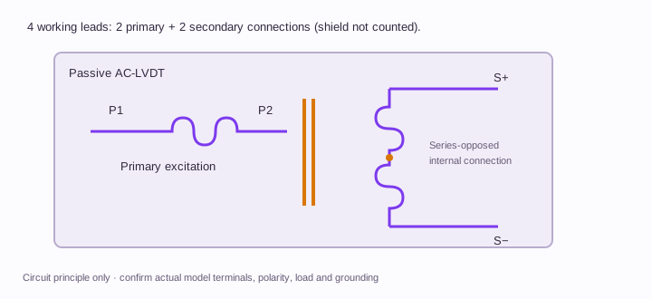
Two primary leads and two differential secondary leads. The secondary polarity is established by the internal winding connection.
Open circuit at full size ↗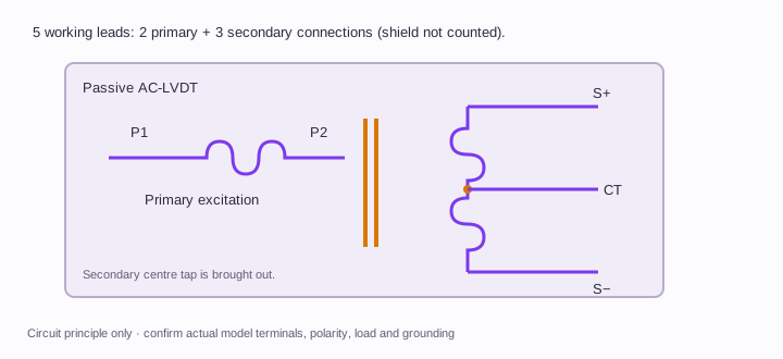
Two primary leads and three secondary connections including the centre tap. A fifth conductor may serve another purpose on some original models.
Open circuit at full size ↗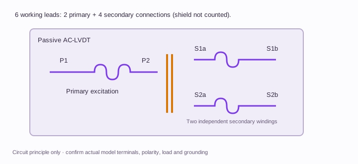
The conditioner receives the primary pair and two independent secondary pairs. Follow its polarity and calculation-mode requirements; no universal external jumper is implied.
Open circuit at full size ↗P1/P2 and S1/S2 identify winding functions; they are not physical connector pin positions. Digital RS485 additionally requires supply, reference, polarity, termination and register-map confirmation. Orbit needs its own network interface.
Full connection guide and original-model pin example ↗MECHANICAL SELECTION
Separate the moving core from the coil body. External guidance must maintain clearance; the electromagnetic sensing element has no sliding electrical contact.
A guided assembly simplifies linkage. Review side load, rod alignment, bearings and usable travel before integrating.
A contact tip follows the measured surface. Review tip force, pre-travel, overtravel and contact wear.
Concept schematics. Non-contact induction does not make bearings, springs or contact tips wear-free.
OPERATING CONDITIONS TO SEND WITH THE RFQ
Illustrative requirement checklists for engineering review. Supply your actual operating conditions and acceptance limits.
Provide radial/axial travel, sensor mounting geometry, chamber medium and pressure, temperature and feedthrough. Do not infer pressure suitability from a miniature body.
State gauge length, expected displacement, heating exposure and specimen attachment. Report how specimen displacement will be separated from fixture expansion or bending.
Give stroke, motion frequency, acceleration, core mass limit and cable clearance. State the required dynamic response of the complete sensor/electronics chain.
AGREE THE METHOD BEFORE THE ORDER
Proposed review steps. The quotation and agreed test plan define the actual test points, conditions, tolerances and deliverables.
Check the agreed datum, attachment, core clearance and cable path through the required travel before energizing the measurement chain.
Record excitation voltage/frequency, cable, conditioner and filtering with the reference displacement. Keep the calibration conditions attached to the result.
Check zero return, bidirectional residuals and the defined dynamic or chamber condition. A room-temperature bench result does not establish chamber-pressure performance.
These steps are a planning framework. No measured LVP data or completed qualification is represented.
REQUEST A CONFIGURATION REVIEW
LVP-MIN · Miniature & Micro LVDT Sensors
Choose the required configuration, then add the mounting envelope, environment and original model. Drawings, compatibility and commercial scope are confirmed with the quotation.
inquiry@lvdtsensor.com ↗The complete core, extension rod and attachment determine moving mass. Request their configuration-specific mass and dimensions; a diameter label alone is insufficient.
Review the change with the selected conditioner and calibration method. Cable loading and the new assembled chain must be assessed; preserve the original cable information.
They correspond to 4.7625 mm and 9.525 mm nominal conversions. Actual housing tolerances and clamping clearance must come from the released drawing.
No. The listed values define the selection request envelope. The quote and released drawing identify the exact range, body size, electrical interface and acceptance conditions.
Yes. Include your installation envelope and required file format in the RFQ. Configuration-specific documentation follows engineering review; an illustration on this page is not a release drawing.
Review the sensor manufacturer’s mounting recommendations. Magnetic materials and excessive clamping force can affect some designs. Specify the clamp material, bore tolerance and torque rather than assuming every metal clamp is unsuitable.
Provide the configuration, quantity and delivery destination. Engineering will confirm the quotation, available documentation and schedule for that request.
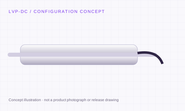
LVP-DC
±2.5 to ±500 mm
4–20 mA · 0–10 V · ±10 V · RS485
Explore configuration ↗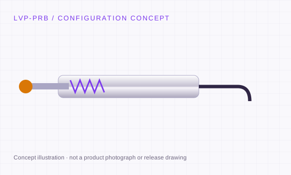
LVP-PRB
±0.5 to ±25 mm
AC · half-bridge · DC · digital variants
Explore configuration ↗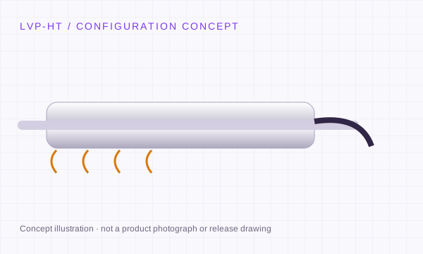
LVP-HT
±2.5 to ±300 mm
Passive AC · remote LVP-AMP
Explore configuration ↗
LVP-AMP
1 / 2.5 / 5 / 10 kHz excitation requests
0–10 V · ±10 V · 4–20 mA · RS485
Explore configuration ↗