INDUCTIVE DISPLACEMENT / OEM CONFIGURATIONinquiry@lvdtsensor.com
LVDTPRECISION METROLOGY

LVP-HT / Passive AC

High-Temperature AC-LVDT Transducers

Passive AC displacement transducer configurations with remote signal conditioning for hot valves, hydraulic test systems and harsh-environment development. Review temperature and pressure together.

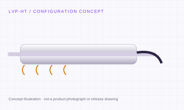
High-Temperature AC-LVDT Transducers concept showing the mechanical form
Engineering concept · final geometry requires a released drawing.

LVP-HT / DEFINE THE INTEGRATION

Review temperature and pressure as one duty profile.

The operating limit belongs to a complete assembly at stated conditions. Describe the hot zone, pressure boundary, media, cable transition and electronics location before selecting a requested temperature or pressure.

01

Continuous temperature or a short peak?

Supply hot-zone temperature versus time, dwell, cycles, ramp rate and cold-end conditions. State where temperatures are measured on the coil, cable transition and connector.

Requests to 220°C or 350°C are review targets; a headline peak temperature does not establish continuous duty.

02

What carries the pressure boundary?

Define operating/proof conditions, pressure direction, fluid, sealing surface, thread or flange, trapped volumes and the required leak-test method.

A 250 bar request is not a rating at every temperature, medium or mounting arrangement.

03

How far away is the conditioner?

Locate the electronics outside its reviewed temperature exposure. Provide carrier, cable length, feedthrough, screen and the existing control-card requirements.

Passive AC construction alone does not establish qualification for steam, subsea, radiation, aviation or nuclear service.

Separate the hot sensing assembly from the cool electronics.

Mounting and thermal expansion
Request a temperature-qualified metal or flange mounting arrangement. State differential movement between valve, bracket, body and core; polymer accessory clamps are excluded from the HT RFQ.
Cable transition and medium
Identify every wetted part, cable sheath and feedthrough. Provide exposure to oil, steam, water or chemicals and the permitted cable bend and restraint at temperature.
Original control-card interface
For retrofit work, include the full sensor suffix, original core, excitation, winding topology, sensitivity and phase requirements. Review the entire feedback chain before change approval.

Technical background for these interface distinctions. Manufacturer references do not establish LVP ratings.

LVP-HT: stroke, body and signal review.

Requested measuring range
±2.5 to ±300 mm
Body / installation
316L / Inconel housing by configuration
Signal variants
Passive AC · remote LVP-AMP
Mechanical configuration
Free core or application-specific guided assembly

Requests to 220°C, optional 350°C or 250 bar are configuration targets, not simultaneous certified ratings.

Confirm these three details before release.

  1. Provide continuous and peak temperatures, dwell time and thermal cycling; specify a temperature-qualified metal mounting arrangement.
  2. For requests to 350°C or 250 bar, specify medium, seals and simultaneous duty.
  3. Radiation, nuclear and aerospace use requires a defined qualification plan.

Where the configuration fits.

Steam-turbine valve development, hot materials tests, hydraulic pressure systems and aerospace actuator research.

Original model review: Macro Sensors HSTA / HSTAR; Honeywell / Kavlico; turbine feedback configurations. References identify review candidates; compatibility is not pre-approved.

Check the replacement process ↗

REQUEST A DEFINED CONFIGURATION

LVP-HT: choose travel, body and interface together.

These request references prefill your RFQ. They describe the configuration you want quoted; final model number, A/B dimensions, thread, performance and availability are confirmed on the quotation drawing.

LVP-HT requested configurations · bipolar range and total travel shown separately
Request referenceRequested travelBody / mechanicsRequested interfaceDrawing & review
LVP-HT-REQ-2P5 ↗±2.5 mm (5 mm total / 0.197 in)19.05 mm (3/4 in)
Free unguided core
Passive AC-LVDT + matched conditionerTemperature, pressure, material and mounting require joint review
LVP-HT-REQ-10 ↗±10 mm (20 mm total / 0.787 in)19.05 mm (3/4 in)
Free unguided core
Passive AC-LVDT + matched conditionerTemperature, pressure, material and mounting require joint review
LVP-HT-REQ-25 ↗±25 mm (50 mm total / 1.969 in)19.05 mm (3/4 in)
Free unguided core
Passive AC-LVDT + matched conditionerTemperature, pressure, material and mounting require joint review
LVP-HT-REQ-50 ↗±50 mm (100 mm total / 3.937 in)19.05 mm (3/4 in)
Free unguided core
Passive AC-LVDT + matched conditionerTemperature, pressure, material and mounting require joint review
LVP-HT-REQ-100 ↗±100 mm (200 mm total / 7.874 in)19.05 mm (3/4 in)
Free unguided core
Passive AC-LVDT + matched conditionerTemperature, pressure, material and mounting require joint review
LVP-HT-REQ-200 ↗±200 mm (400 mm total / 15.748 in)19.05 mm (3/4 in)
Free unguided core
Passive AC-LVDT + matched conditionerTemperature, pressure, material and mounting require joint review
LVP-HT-REQ-300 ↗±300 mm (600 mm total / 23.622 in)19.05 mm (3/4 in)
Free unguided core
Passive AC-LVDT + matched conditionerTemperature, pressure, material and mounting require joint review

Set the installation envelope before dimensions A and B.

Provide maximum body length, core or rod length, datum-to-null distance, thread, connector clearance and permitted overtravel. Dimension letters differ between original manufacturers. Use the exact released drawing for an installation comparison.

Compare a source-linked original model ↗

TAKE THE CONFIGURATION TO YOUR ENGINEERING TEAM

LVP-HT selection worksheet.

Download the family guide, requested configurations and editable RFQ fields. Fill in the PDF, save it in your reader and email the saved file to inquiry@lvdtsensor.com.

Preliminary selection worksheet. Configuration-specific dimensions, ratings, released CAD and measured reports follow review.

EXCITATION & CONNECTION TOPOLOGY

Count the electrical functions before the wires.

Use these circuit principles to identify the required sensor and conditioner. Cable colour, shield count and connector shell do not establish a pinout.

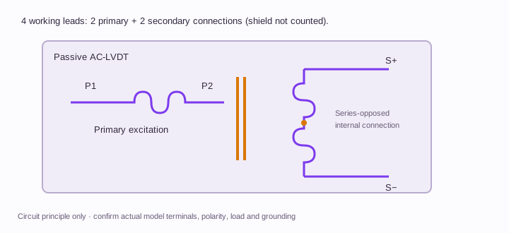
4-wire AC · internal series connection

4-wire AC · internal series connection circuit principle; Two primary leads and two differential secondary leads. The secondary polarity is established by the internal winding connection.

Two primary leads and two differential secondary leads. The secondary polarity is established by the internal winding connection.

Open circuit at full size ↗

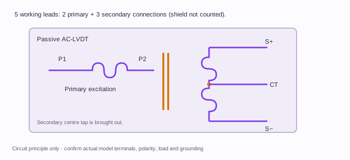
5-wire AC · secondary centre tap

5-wire AC · secondary centre tap circuit principle; Two primary leads and three secondary connections including the centre tap. A fifth conductor may serve another purpose on some original models.

Two primary leads and three secondary connections including the centre tap. A fifth conductor may serve another purpose on some original models.

Open circuit at full size ↗

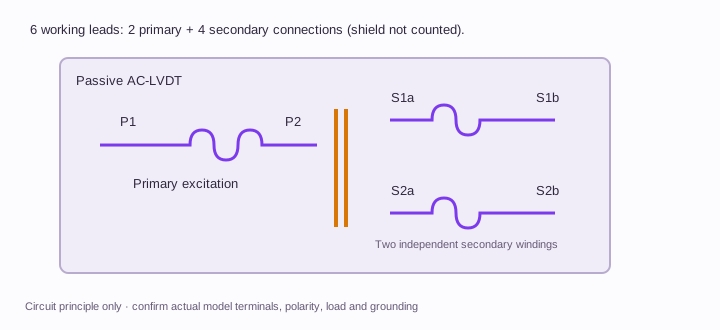
6-wire AC · independent secondaries

6-wire AC · independent secondaries circuit principle; The conditioner receives the primary pair and two independent secondary pairs. Follow its polarity and calculation-mode requirements; no universal external jumper is implied.

The conditioner receives the primary pair and two independent secondary pairs. Follow its polarity and calculation-mode requirements; no universal external jumper is implied.

Open circuit at full size ↗

P1/P2 and S1/S2 identify winding functions; they are not physical connector pin positions. Digital RS485 additionally requires supply, reference, polarity, termination and register-map confirmation. Orbit needs its own network interface.

Full connection guide and original-model pin example ↗

MECHANICAL SELECTION

Free core, guided rod or spring contact?

Free unguided core

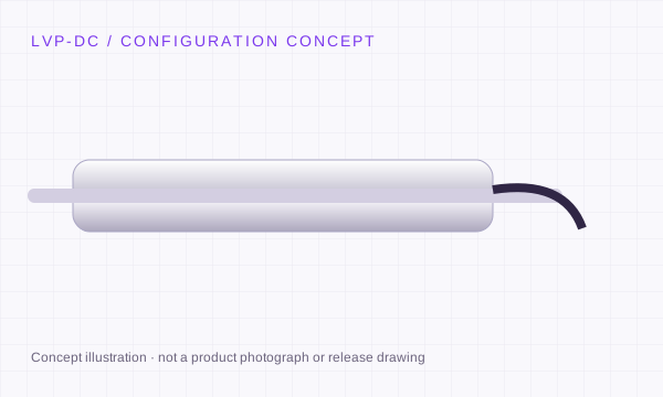
Separate the moving core from the coil body. External guidance must maintain clearance; the electromagnetic sensing element has no sliding electrical contact.

Captive guided rod

A guided assembly simplifies linkage. Review side load, rod alignment, bearings and usable travel before integrating.

Spring-return probe

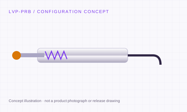
A contact tip follows the measured surface. Review tip force, pre-travel, overtravel and contact wear.

Concept schematics. Non-contact induction does not make bearings, springs or contact tips wear-free.

OPERATING CONDITIONS TO SEND WITH THE RFQ

LVP-HT: define the installation behind the travel.

Illustrative requirement checklists for engineering review. Supply your actual operating conditions and acceptance limits.

Steam-turbine valve development

Submit hot/cold valve travel, mounting expansion, vibration, cable routing and the control-card details. Define the operating and outage inspection conditions.

Hydraulic cylinder or pressure rig

Supply medium, pressure profile, seal design, temperature and installation orientation. Define proof/leak-test requirements with the responsible assembly designer.

Aerospace or nuclear evaluation

Provide the applicable qualification plan, environmental tests, redundancy and traceability requirements. This page supplies no flight, nuclear or protective-system approval.

Send the installation and documentation requirements ↗

AGREE THE METHOD BEFORE THE ORDER

What should the LVP-HT acceptance record contain?

Proposed review steps. The quotation and agreed test plan define the actual test points, conditions, tolerances and deliverables.

  1. Approve the joint duty profile

    Record the configuration drawing, materials, seals, cable and agreed simultaneous thermal/pressure conditions. Confirm the method and responsible test organization before ordering.

  2. Measure before and after exposure

    Plan baseline displacement checks, the specified exposure sequence and post-exposure checks. Define zero shift, sensitivity change and acceptance limits in advance.

  3. Test the complete boundary

    Use the agreed pressure/leak and electrical checks for the released assembly. A coil-only test or room-temperature pressure result cannot establish the whole duty profile.

These steps are a planning framework. No measured LVP data or completed qualification is represented.

REQUEST A CONFIGURATION REVIEW

Define the travel.
Match the mechanics.
Keep the signal clear.

LVP-HT · High-Temperature AC-LVDT Transducers

Choose the required configuration, then add the mounting envelope, environment and original model. Drawings, compatibility and commercial scope are confirmed with the quotation.

inquiry@lvdtsensor.com ↗
Need STEP / IGES or a dimensional drawing? State the file format and fixed mounting dimensions. Configuration references are selection requests; final dimensions and ratings follow engineering review.
LVDT engineering RFQ
Attach a drawing, CAD file or nameplate (optional)

PDF, STEP/STP, IGES/IGS, DXF, PNG or JPG. Up to 4 files; 5 MiB each, 8 MiB combined. Files travel with this RFQ to inquiry@lvdtsensor.com; no public file link is created.

Documents to request with the configuration

Availability, scope and file revision follow review. These selections request documents; attach your own files above.

Specify a temperature-qualified metal or flange mounting arrangement. Polymer clamp blocks are excluded from this high-temperature request.

Complete the installation.

Accessory references in USD per single set, quoted separately from the sensor. Quantity, custom machining and any NRE are confirmed on the quotation.

Accessory budget per single set: $245Not an order total. Primary sensor / equipment, NRE, tax and freight excluded. No payment at this stage.

Before ordering LVP-HT.

Can I combine 350°C and 250 bar from the request list?

Those are separate configuration targets until a simultaneous duty profile is reviewed. Medium, seals, materials, cable transitions and test method must be confirmed together.

Why is the conditioner outside the hot zone?

A passive AC sensing assembly can be evaluated separately from its electronics. State the temperature at the actual conditioner and cable transition; neither component inherits the other’s rating.

Does a high-temperature LVDT have aerospace or nuclear certification?

No such qualification is implied. Provide the applicable programme, required evidence and responsible acceptance authority for a separate review.

Are the listed ranges guaranteed for every configuration?

No. The listed values define the selection request envelope. The quote and released drawing identify the exact range, body size, electrical interface and acceptance conditions.

Can I request a CAD drawing and calibration information?

Yes. Include your installation envelope and required file format in the RFQ. Configuration-specific documentation follows engineering review; an illustration on this page is not a release drawing.

Which mounting arrangement is suitable in the hot zone?

Request a temperature-qualified metal or flange arrangement. Confirm material, thermal expansion and permitted clamping force from the configuration drawing; polymer accessory clamps are excluded from the high-temperature RFQ.

What are the price, minimum quantity and lead time?

Provide the configuration, quantity and delivery destination. Engineering will confirm the quotation, available documentation and schedule for that request.

Complete the LVDT measurement chain.