DIN-rail carrier amplifiers, signal conditioners and micrometer fixtures for AC-LVDT integration, scaling and calibration planning. Match the transformer before selecting an output.
Match the inductive input before choosing the PLC output.
A carrier conditioner request begins with the sensor and cable it must drive. A calibration-fixture request begins with the reference displacement and uncertainty needed. Treat the electronics and mechanical reference as distinct parts of the chain.
01
Which transformer or bridge input?
Supply the exact probe/core model, topology, excitation amplitude/frequency, sensitivity, phase requirements and cable load. Include the existing input schematic.
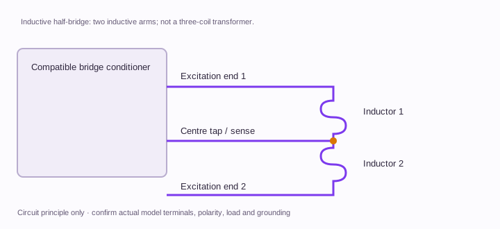
A 3-wire half-bridge is not established as compatible with a generic 4/5/6-wire LVDT module.
02
What output and channel behaviour?
Define the receiver load, zero/span mapping, output polarity, filtering and update interval. For multiple channels, request synchronization and review interaction tests.
An RS485 connector does not define the register map, and a DIN-rail enclosure does not establish isolation.
03
What does the calibration fixture need to cover?
Give full required travel, alignment, reference instrument, uncertainty target and fixture clearances. Identify how the sensor, core and reference will be mounted.
A 0–25 mm fixture permits only the applicable travel; 0.001 mm readout resolution is not an accuracy or traceability statement.
Keep calibration identity with the complete signal chain.
Controller and receiver integration
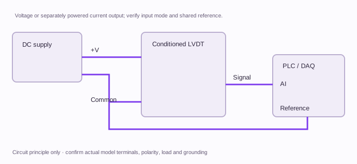
Specify input load, grounding, output fault behaviour and required access to zero/span adjustments. Confirm terminal functions on the selected module drawing.
Channel interaction
List channel count, neighbouring carrier sources and cable routing. Ask for an agreed synchronization architecture and check the assembled system under representative channel operation.
Reference and recording method
Identify reference instrument serial, calibration status, datum, direction, temperature and uncertainty evaluation. Keep each sensor/core, cable and conditioner identity with the recorded data.
Technical background for these interface distinctions. Manufacturer references do not establish LVP ratings.
LVP-AMP: choose travel, body and interface together.
These request references prefill your RFQ. They describe the configuration you want quoted; final model number, A/B dimensions, thread, performance and availability are confirmed on the quotation drawing.
LVP-AMP requested configurations · bipolar range and total travel shown separately
0–25 mm bench fixture request; uncertainty and alignment to review
Set the installation envelope before dimensions A and B.
Provide maximum body length, core or rod length, datum-to-null distance, thread, connector clearance and permitted overtravel. Dimension letters differ between original manufacturers. Use the exact released drawing for an installation comparison.
Download the family guide, requested configurations and editable RFQ fields. Fill in the PDF, save it in your reader and email the saved file to inquiry@lvdtsensor.com.
Preliminary selection worksheet. Configuration-specific dimensions, ratings, released CAD and measured reports follow review.
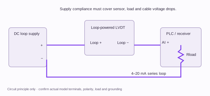
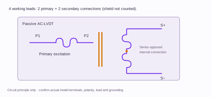
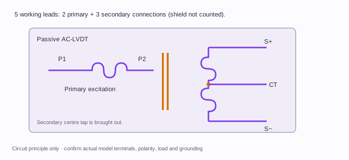
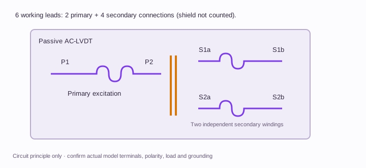
Use these circuit principles to identify the required sensor and conditioner. Cable colour, shield count and connector shell do not establish a pinout.
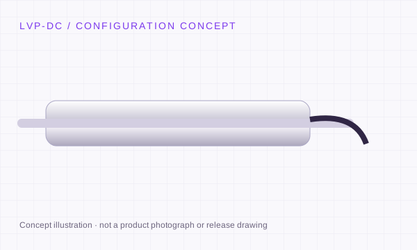
2-wire DC · loop powered
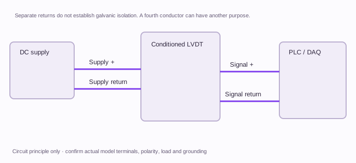
The loop supply, sensor and receiving load form one series circuit. Check minimum sensor voltage, receiver burden and maximum cable drop.
The conditioner receives the primary pair and two independent secondary pairs. Follow its polarity and calculation-mode requirements; no universal external jumper is implied.
A bridge conditioner excites two inductive arms. Match the bridge type, carrier, sensitivity and completion circuit; it is not a generic AC-LVDT input.
P1/P2 and S1/S2 identify winding functions; they are not physical connector pin positions. Digital RS485 additionally requires supply, reference, polarity, termination and register-map confirmation. Orbit needs its own network interface.
LVP-AMP: define the installation behind the travel.
Illustrative requirement checklists for engineering review. Supply your actual operating conditions and acceptance limits.
PLC conversion of an existing AC sensor
Provide the original datasheet, carrier, sensitivity and wiring diagram with desired current/voltage/digital output. Request scaling at the actual physical endpoints.
Multi-point gauging cabinet
Provide channel count, sample sequence, permitted delay, cables and controller/network. Define stationary noise and channel-interaction checks before a module is selected.
Bench calibration or electrical simulation
Separate mechanical sensor travel checks from an electrical simulator test of the conditioner. A simulated input cannot establish the sensor’s physical linearity or repeatability.
What should the LVP-AMP acceptance record contain?
Proposed review steps. The quotation and agreed test plan define the actual test points, conditions, tolerances and deliverables.
Agree the input and output mapping
Confirm sensor excitation and input topology, then define the requested output at the reference travel points and the receiving load.
Record the mechanical comparison
Use the agreed reference, alignment and travel sequence. Keep raw readings before/after adjustment and the calculation method for residuals and repeatability.
Evaluate measurement uncertainty
Document relevant contributions, reference-chain evidence and coverage method. A completed blank worksheet is not a calibration certificate or an accreditation claim.
These steps are a planning framework. No measured LVP data or completed qualification is represented.
REQUEST A CONFIGURATION REVIEW
Define the travel. Match the mechanics. Keep the signal clear.
Choose the required configuration, then add the mounting envelope, environment and original model. Drawings, compatibility and commercial scope are confirmed with the quotation.
Need STEP / IGES or a dimensional drawing? State the file format and fixed mounting dimensions. Configuration references are selection requests; final dimensions and ratings follow engineering review.
Before ordering LVP-AMP.
Can one LVDT conditioner accept any inductive probe?
Only after the input topology, carrier, sensitivity, phase and cable requirements are matched. Separate half-bridge or proprietary digital interfaces need a specifically reviewed solution.
Does the micrometer stand produce a traceable calibration certificate?
The stand alone does not. A measurement result needs a documented reference chain, method and uncertainty evaluation. Request the required calibration scope and report contents.
What does an LVDT simulator verify?
It can support electrical checks of a compatible conditioner input and scaling. It does not move the actual core or prove physical sensor linearity, mounting behaviour or repeatability.
Are the listed ranges guaranteed for every configuration?
No. The listed values define the selection request envelope. The quote and released drawing identify the exact range, body size, electrical interface and acceptance conditions.
Can I request a CAD drawing and calibration information?
Yes. Include your installation envelope and required file format in the RFQ. Configuration-specific documentation follows engineering review; an illustration on this page is not a release drawing.
Does one conditioner support every inductive sensor?
Match the excitation, sensitivity, winding topology, cable load and output. Half-bridge and proprietary digital probes require separate interface review. A common conductor count does not establish compatibility.
What are the price, minimum quantity and lead time?
Provide the configuration, quantity and delivery destination. Engineering will confirm the quotation, available documentation and schedule for that request.