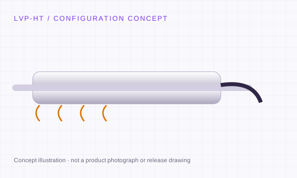
Spring-return and pneumatic gauging probe configurations for multi-point fixtures, thickness stations and dimensional inspection. Match tip force and guidance to the measured surface.
Engineering concept · final geometry requires a released drawing.
LVP-PRB: stroke, body and signal review.
Requested measuring range
±0.5 to ±25 mm
Body / installation
Ø8 h6 / Ø9.525 mm
Signal variants
AC · half-bridge · DC · digital variants
Mechanical configuration
Spring return or pneumatic actuation
Resolution and repeatability depend on the complete measurement chain and test method. Conditioned DC/digital probes may use an in-line electronics module; agree its installation envelope separately.
Confirm these three details before release.
Request repeatability at a defined contact force, approach direction and test method.
Choose M2.5 or #4-48 tip threads from the exact probe drawing.
Orbit and half-bridge interfaces require separate controller compatibility review.
Where the configuration fits.
Automotive components, bearing inspection, glass thickness and precision gauging fixtures.
Original model review: Solartron AX / DP; Macro Sensors GHSA / GHSDR; Mahr, Marposs and Tesa probe configurations. References identify review candidates; compatibility is not pre-approved.
Choose the contact force before the displayed resolution.
A gauging probe becomes a measurement system only after its tip, fixture, electronics and operating cycle are defined. The useful comparison is repeatability under the intended contact and return conditions.
01
Spring return or pneumatic actuation?
State measurement orientation, approach sequence, contact force through the working travel and retraction clearance. For pneumatic requests, provide pressure regulation and the required air-quality specification.
Do not copy an air-pressure setting from a different probe or actuator design.
02
Ball, flat, ruby or roller contact?
Describe the surface, material, contact geometry, tip thread and whether the part moves under the tip. Include coolant, chips and cleaning exposure.
A tip selected only by thread size can still impose the wrong contact force or side load.
03
LVDT, half-bridge or digital network?
Identify the existing input card and full probe model. Confirm carrier, sensitivity and winding topology, or request the digital protocol/interface.
A shared Ø8 mm body does not make analogue, half-bridge and Orbit probes electrically interchangeable.
Preserve the guidance when the fixture closes.
Clamping and overtravel
Specify clamping-zone length, bore tolerance, permitted clamp force and travel stops. Avoid assuming that the measuring range includes all approach and emergency overtravel.
Contact on fragile or moving surfaces
Define the allowed surface marking and normal/lateral force. Review the complete tip and guidance arrangement where sliding contact or material movement is continuous.
Multiple probes in one station
List channel count, cable routing, sample timing and nearby excitation sources. Agree how electrical noise and channel interactions will be checked in the assembled gauge.
Technical background for these interface distinctions. Manufacturer references do not establish LVP ratings.
LVP-PRB: choose travel, body and interface together.
These request references prefill your RFQ. They describe the configuration you want quoted; final model number, A/B dimensions, thread, performance and availability are confirmed on the quotation drawing.
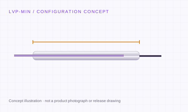
LVP-PRB requested configurations · bipolar range and total travel shown separately
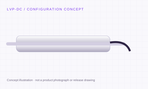
Long-travel probe request; overall length, force and guidance to review
Set the installation envelope before dimensions A and B.
Provide maximum body length, core or rod length, datum-to-null distance, thread, connector clearance and permitted overtravel. Dimension letters differ between original manufacturers. Use the exact released drawing for an installation comparison.
Download the family guide, requested configurations and editable RFQ fields. Fill in the PDF, save it in your reader and email the saved file to inquiry@lvdtsensor.com.
Preliminary selection worksheet. Configuration-specific dimensions, ratings, released CAD and measured reports follow review.
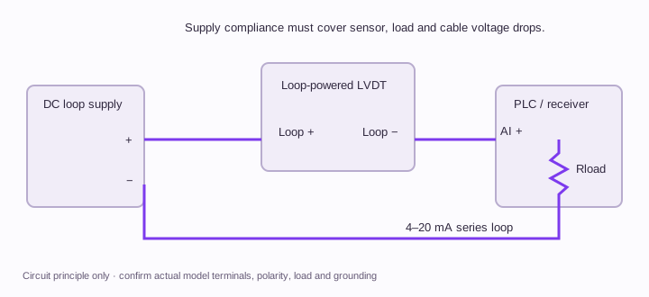
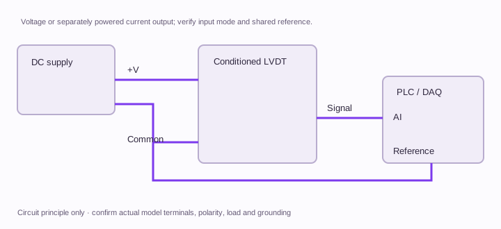
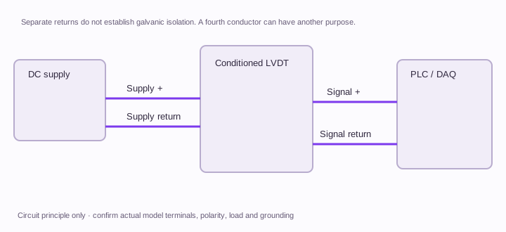
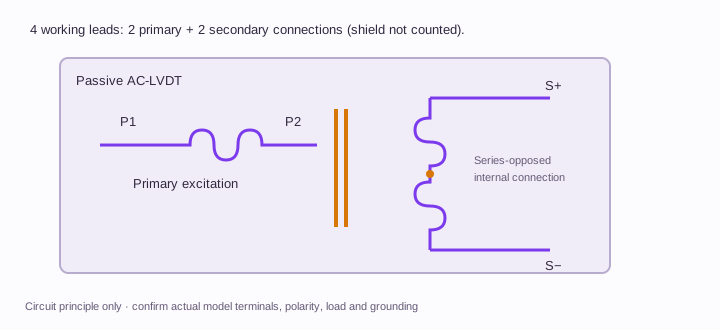
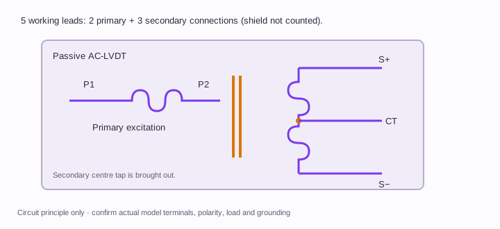
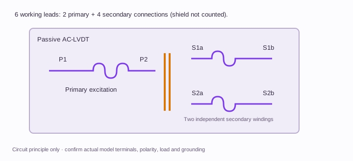
Use these circuit principles to identify the required sensor and conditioner. Cable colour, shield count and connector shell do not establish a pinout.
2-wire DC · loop powered
The loop supply, sensor and receiving load form one series circuit. Check minimum sensor voltage, receiver burden and maximum cable drop.
The conditioner receives the primary pair and two independent secondary pairs. Follow its polarity and calculation-mode requirements; no universal external jumper is implied.
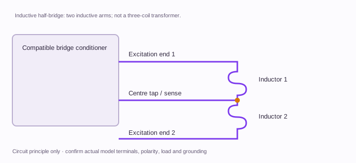
A bridge conditioner excites two inductive arms. Match the bridge type, carrier, sensitivity and completion circuit; it is not a generic AC-LVDT input.
P1/P2 and S1/S2 identify winding functions; they are not physical connector pin positions. Digital RS485 additionally requires supply, reference, polarity, termination and register-map confirmation. Orbit needs its own network interface.
Separate the moving core from the coil body. External guidance must maintain clearance; the electromagnetic sensing element has no sliding electrical contact.
Captive guided rod
A guided assembly simplifies linkage. Review side load, rod alignment, bearings and usable travel before integrating.
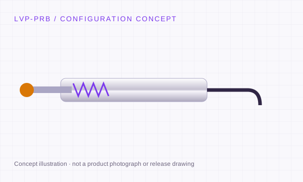
Spring-return probe
A contact tip follows the measured surface. Review tip force, pre-travel, overtravel and contact wear.
Concept schematics. Non-contact induction does not make bearings, springs or contact tips wear-free.
CONTACT-PROBE FORM REFERENCE
Review the tip, body and installation envelope together.
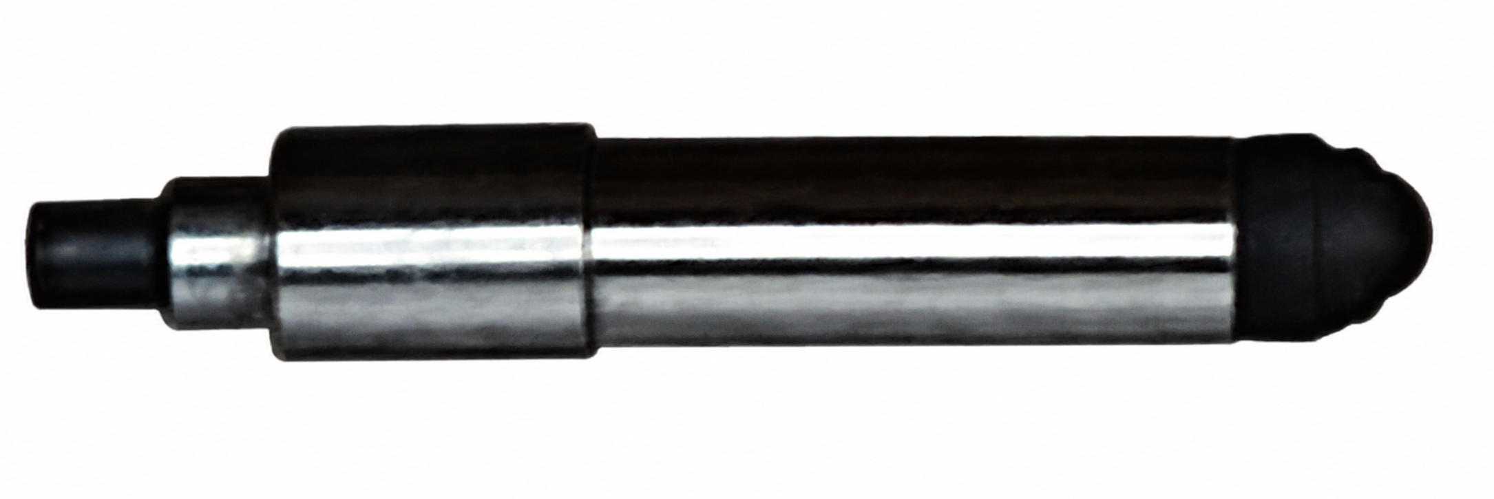
A supplier catalogue example helps identify the mechanical form to discuss. Supply a nameplate or drawing in the RFQ for the actual configuration review.
Supplier-derived catalogue reference, prepared from authorized source material. This is not a released LVP model photograph or evidence of dimensions, interface, performance or supply availability.Attach the actual probe drawing or nameplate ↗
OPERATING CONDITIONS TO SEND WITH THE RFQ
LVP-PRB: define the installation behind the travel.
Illustrative requirement checklists for engineering review. Supply your actual operating conditions and acceptance limits.
Bearing or machined-component gauge
Provide datum locations, allowable error, part loading sequence and master artefact information. Include fixture repeatability and the required gauge R&R study scope.
Glass or battery-material thickness
Give thickness range, fragility, surface finish and whether material is stationary or moving. Specify one-sided or opposed-tip geometry and allowable contact force.
Long-travel or pneumatic access
State approach travel separately from measurement travel and include overall-length restrictions. The ±25 mm request needs a reviewed force, guidance and installation envelope.
What should the LVP-PRB acceptance record contain?
Proposed review steps. The quotation and agreed test plan define the actual test points, conditions, tolerances and deliverables.
Fix the contact conditions
Record tip type, contact force, orientation, air settings and the actual master surface. Define the return/approach sequence before collecting readings.
Separate noise from mechanical return
Record stationary noise and repeated lift/return readings using the selected electronics and filtering. State repeats and the repeatability calculation used.
Verify the assembled station
Repeat after clamping and with adjacent channels operating. Probe-level observations do not establish the capability of the entire production gauge.
These steps are a planning framework. No measured LVP data or completed qualification is represented.
REQUEST A CONFIGURATION REVIEW
Define the travel. Match the mechanics. Keep the signal clear.
LVP-PRB · Spring-Loaded LVDT Gauging Probes
Choose the required configuration, then add the mounting envelope, environment and original model. Drawings, compatibility and commercial scope are confirmed with the quotation.
Need STEP / IGES or a dimensional drawing? State the file format and fixed mounting dimensions. Configuration references are selection requests; final dimensions and ratings follow engineering review.
Before ordering LVP-PRB.
Is 0.001 mm resolution a repeatability guarantee?
No. Display increments do not establish repeatability. Agree the contact force, return cycle, fixture, electronics, filtering and calculation method, then request measurement evidence for the selected configuration.
Can I use the same pneumatic pressure for every probe?
Use the pressure and air-quality limits specified for the exact mechanism. Probe extension, retraction and contact force must be reviewed with its orientation and working travel.
Will a replacement connect to my Orbit controller?
The controller and network interface require separate review. A mechanically similar probe or an RS485 output does not establish Orbit compatibility.
Are the listed ranges guaranteed for every configuration?
No. The listed values define the selection request envelope. The quote and released drawing identify the exact range, body size, electrical interface and acceptance conditions.
Can I request a CAD drawing and calibration information?
Yes. Include your installation envelope and required file format in the RFQ. Configuration-specific documentation follows engineering review; an illustration on this page is not a release drawing.
Do I need a non-magnetic clamp?
Review the sensor manufacturer’s mounting recommendations. Magnetic materials and excessive clamping force can affect some designs. Specify the clamp material, bore tolerance and torque rather than assuming every metal clamp is unsuitable.
What are the price, minimum quantity and lead time?
Provide the configuration, quantity and delivery destination. Engineering will confirm the quotation, available documentation and schedule for that request.